
How to Replace KEYMASTER G3 Motherboard Guide
In this guide, we demonstrate how to replace the KEYMASTER G3 motherboard with this step-by-step repair guide, including disassembly, coil removal, motherboard installation and device testing.
In this guide, we demonstrate how to replace KEYMASTER G3 motherboard with this step-by-step repair guide, including disassembly, coil removal, motherboard installation and device testing.
Disassembly
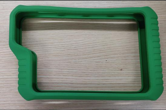
Step 1:a. Remove the rubber case.
b. Use a screwdriver to loosen and remove the hex socket screws
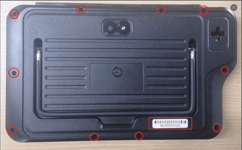
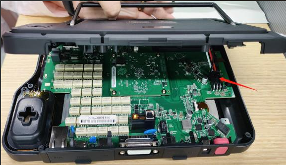
Step 2: Open the back cover and press down on the battery connector clip with your hand, then pull out the battery connector.
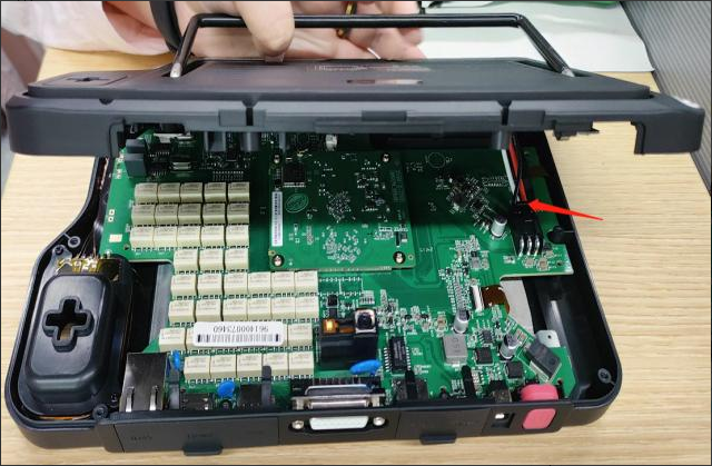
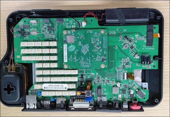
Step 3: Remove the antenna marked by the arrow. Use a screwdriver to loosen the screws
securing the Android board and remove the Android board.
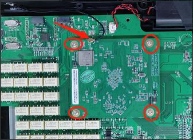
Step 4: Peel off the acetate tape at the screen flex cable connection. Remove the LCD screen
and TP (touch panel) cable, and unplug the speaker cable. Use a screwdriver to loosen the
screws securing the mainboard and the coil, then remove the mainboard and the coil.
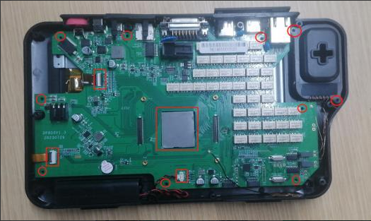
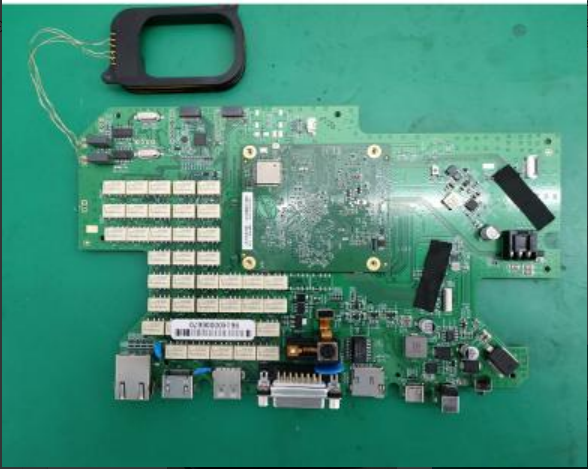
Step 5:
- Set the soldering iron temperature to 350 ± 10°C and desolder the coil to remove it.
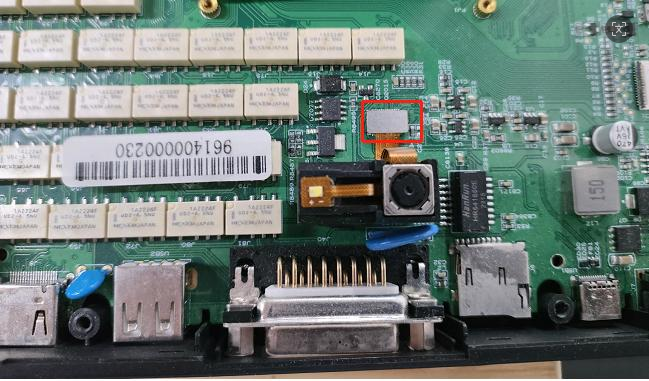
- Unplug the camera flex cable and use a screwdriver to loosen the screws securing the camera, then remove the camera.
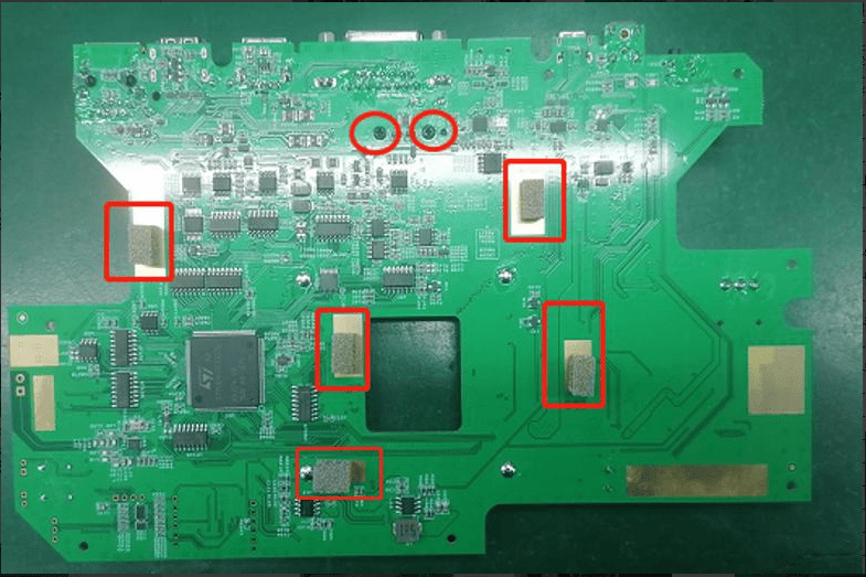
- Peel off the adhesive at the bottom of the conductive foam and remove it. (If the new mainboard comes with conductive foam already attached, this step is not necessary. Be careful when peeling off the conductive foam as it can easily be damaged.) Disassembly is complete.
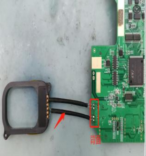
Installation
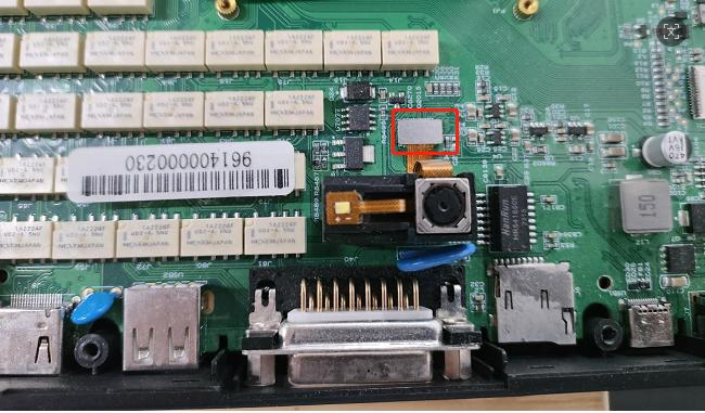
Step 1:- Take the new mainboard, install the camera, secure it with screws, and connect the camera flex cable.
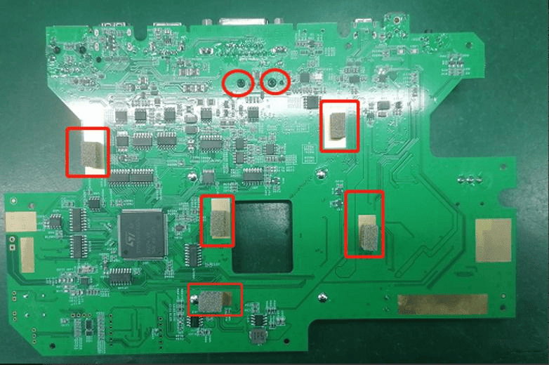
- Attach the conductive foam.
- Insert the Android board and secure it with screws
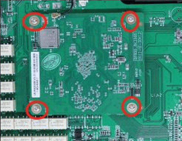
Step 2:
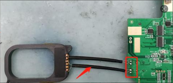
- Set the soldering iron temperature to 350 ± 10°C and solder the coil.
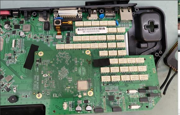
- Keep the screen flex cable clear of the area where the main board will be installed. Align the mainboard with the housing connectors, and ensure the coil is installed before fully securing the mainboard to avoid pulling the wires and causing damage. Then, install the mainboard.
Step 3:
- Use a screwdriver to secure the mainboard with screws.
- Secure the coil bracket with screws.
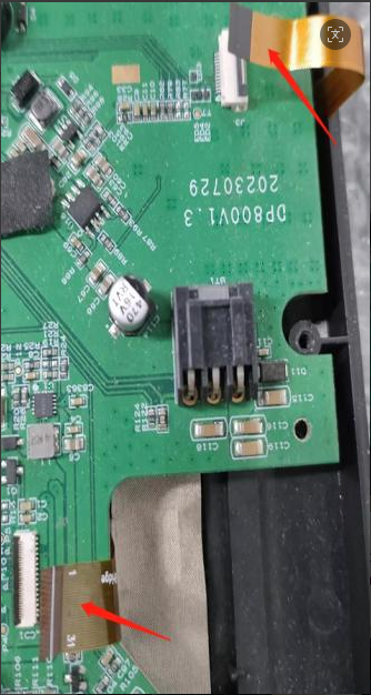
- Connect the LCD screen flex cable and the TP flex cable (with the white line facing up). After connecting, apply acetate tape to both the connector and the flex cable.
- Connect the speaker cable and secure the antenna.
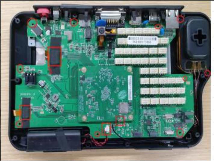
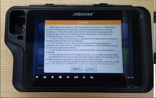
Step 4: Insert the battery connector, reassemble the back cover, and press the power button
to turn on the device. If it starts up normally, the replacement is successful.
Step 5: Use a screwdriver to fasten the screws to the back cover, and put the rubber case
back on. The replacement is complete.
Note:
1. If you cannot boot or have other abnormalities after replacing the Android motherboard, please contact after-sales. You need to provide your device serial number;
2. If the display is abnormal after replacing the display screen, please contact after-salesand provi
de your device serial number;
3. When you need to replace the VCI motherboard, please contact the dealer to synchronize your
account information and provide the serial numbers of the new and old VCI motherboards